
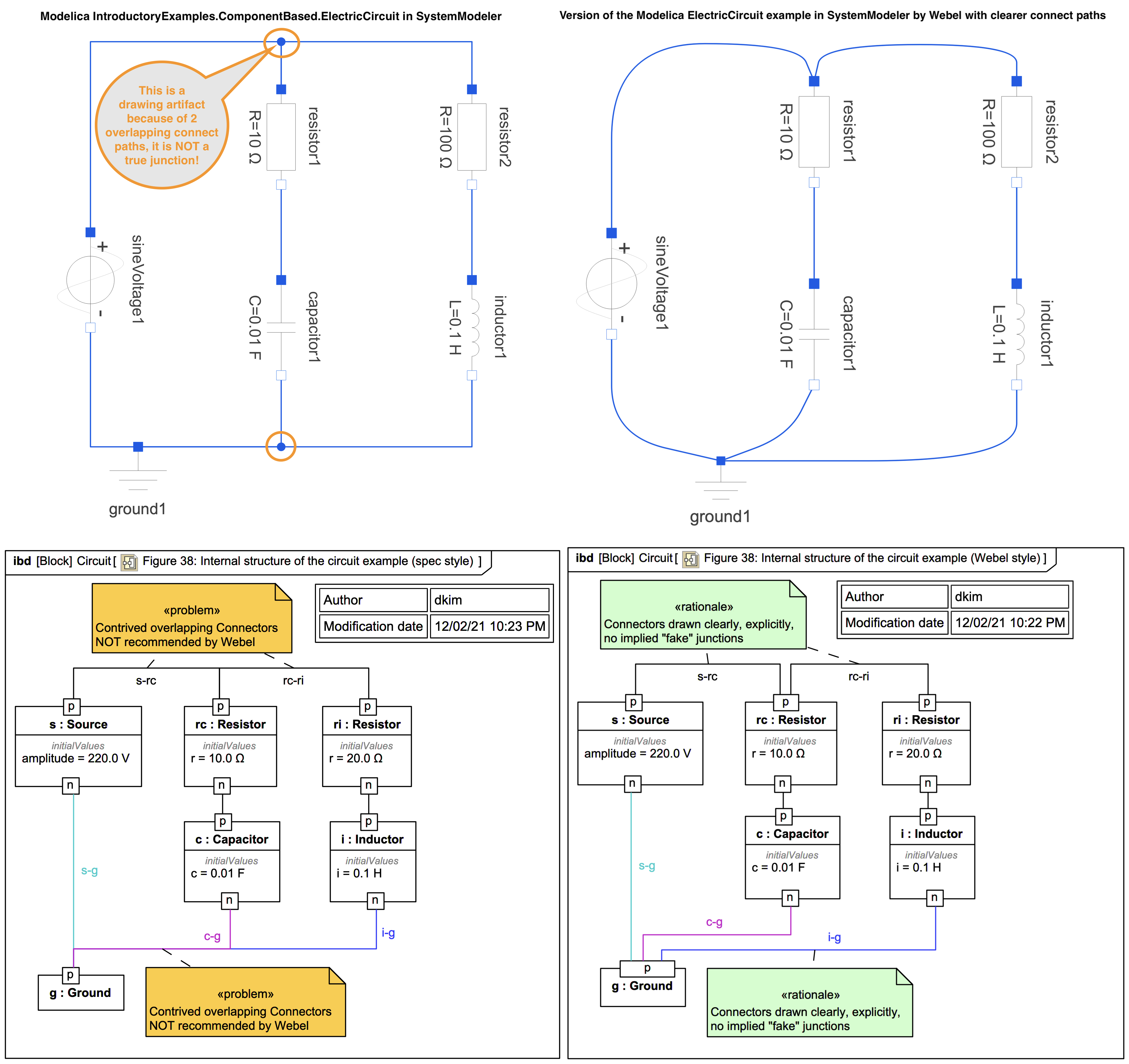
IntroductoryExamples.ComponentBased.ElectricCircuit! They get away with it because the result for the components is the same for "lumped" topological models of electrical circuits but it may give the impression that the Connectors correspond to wires, which they do not, and that there are physical junctions in the diagram that do not exist.
The image top-left is a snapshot of a typical Modelica tool example of ElectricCircuit. The image top-right is the same thing drawn to expose the connect paths clearly, and with no "fake" nodes or junctions. It is not suggested in this trail that you should always draw it that way in Modelica. The point is rather to make it clear what is actually going on behind the scenes in the tool. In most Modelica tools, if you select one of the connect lines it is momentarily highlighted and it becomes clear in the active model diagram shown upper left that there is in fact no node or junction between the positive pins of the source and the two resistors; this is not so clear when the diagram is exported!
The image bottom-left shows the type of similar SysML Connector path overlapping that appears in the SysPhS-1.1 sample Figure 38: Internal structure of the circuit example. Some of the Connectors have additionally been named here, and some of the Connector paths have been coloured, so that you can see clearly how the paths overlap.
Especially when dealing with ItemFlows on Connectors in SysML, this can lead to problems, such as:
The image bottom-right shows the same thing drawn according to Webel Best Practice for SysML and SysPhS with no mystical path overlapping.
There's nothing to stop a modeller including explicit 3-way Junctions that abide by the rules of electricity - and if you were to run the model you'd get exactly the same result - but implying physical nodes that don't exist is not necessary and not good practice.