
This page shows (for purposes of historical reference only) an OBSOLETE early attempt at re-appropriating Unified Modeling Language (UML®) for port-based systems engineering. Please see now instead for latest Systems Modeling Language v1 (SysML®) !
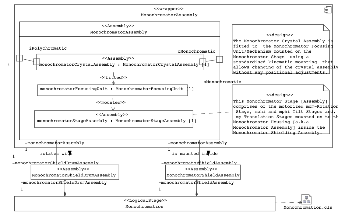
Corresponds roughly to the view from above (the UML diagram can only at best indicate topology, not geometry).
Note also the lack of direction on the typed 'rotates with' and 'is mounted inside' connections compared with the "directed" association names. Compare with the «fitted» and «mounted» Dependencies, which emphasise the time order of construction (assembly) of the components, i.e., that the supplier must exist before the client.