
Tags and keywords
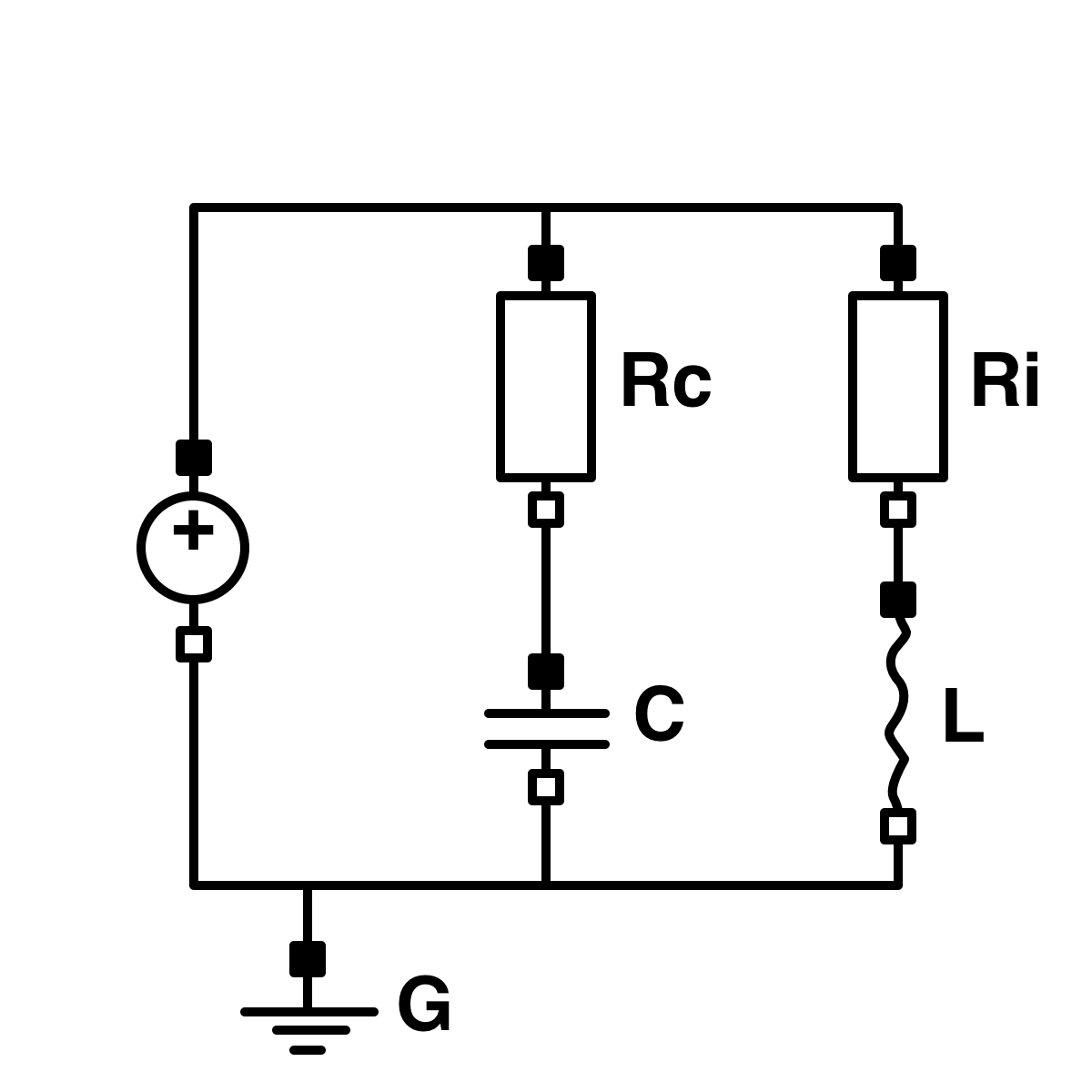
This is not a screenshot of the spec document figure, it's actually been redone in a drawing program (as you can tell from the not so perfect wiggles on the inductor).
But what exactly is it? Is it a wiring diagram? An electrical circuit diagram? An electrical schematic? Most importantly, what do the lines between the positive pins (indicated Modelica-style as small black filled squares) and/or the negative pins (indicated Modelica-style as small black empty squares) stand for?
Throughout this section of the trail the following will be driven home:
Because of the relatively forgiving wonders of Kirchhoff's circuit laws, so-called lumped circuit models are forever being conflated with physical wiring diagrams with perfectly lossless wires. This doesn't usually matter from the topological point of view of circuit design, but it DOES matter from the point of view of precise analysis of SysML/SysPhS model elements!