
Tags and keywords
IntroductoryExamples.ComponentBased.ElectricCircuit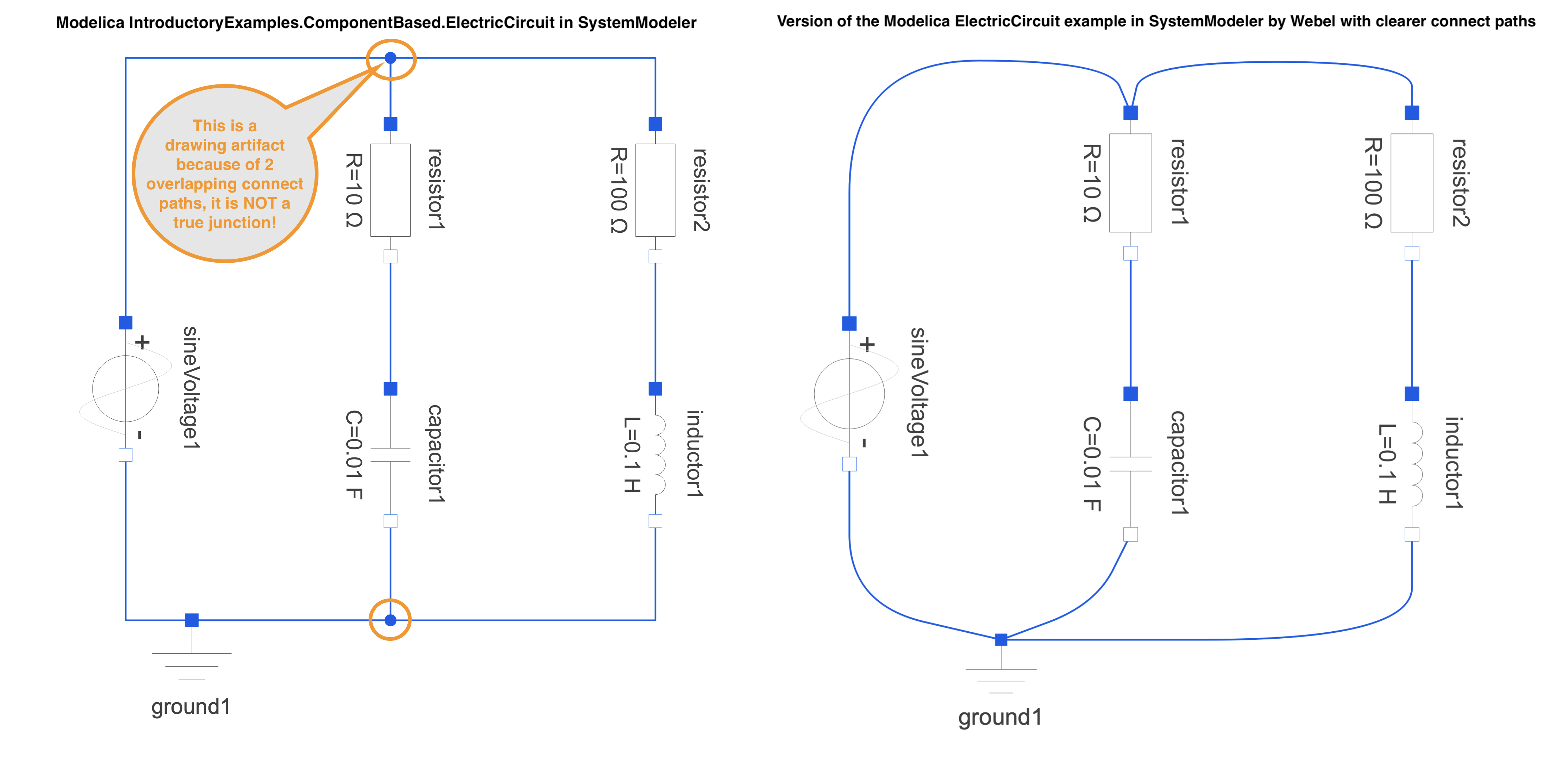
It is not suggested in this trail that you should always draw it that way in Modelica. The point is rather to make it clear what is actually going on behind the scenes in the tool. In most Modelica tools, if you select one of the connect lines it is momentarily highlighted and it becomes clear in the model diagram shown left that there is in fact no node or junction between the positive pins of the source and the two resistors; this is not so clear when the diagram is exported!
One could of course instead introduce an explicit 3-way Junction component.
Let's now reproduce this model using SysML/SysPhS. First we'll create a Block Definition Diagram (BDD) to define the components then we'll mimic the lumped-model electric circuit using an Internal Block Diagram (IBD). (The spec actually shows this done the other way round, with the IBD shown first.)