
Tags and keywords
within Modelica.Thermal.HeatTransfer;
package Interfaces "Connectors and partial models"
  partial connector HeatPort "Thermal port for 1-dim. heat transfer"
    Modelica.SIunits.Temperature T "Port temperature";
    flow Modelica.SIunits.HeatFlowRate Q_flow
      "Heat flow rate (positive if flowing from outside into the component)";
  end HeatPort;

  connector HeatPort_a "Thermal port for 1-dim. heat transfer (filled rectangular icon)"
    extends HeatPort;

    annotation ...
  end HeatPort_a;

  connector HeatPort_b "Thermal port for 1-dim. heat transfer (unfilled rectangular icon)"
    extends HeatPort;

    annotation ...
  end HeatPort_b;
end Interfaces;
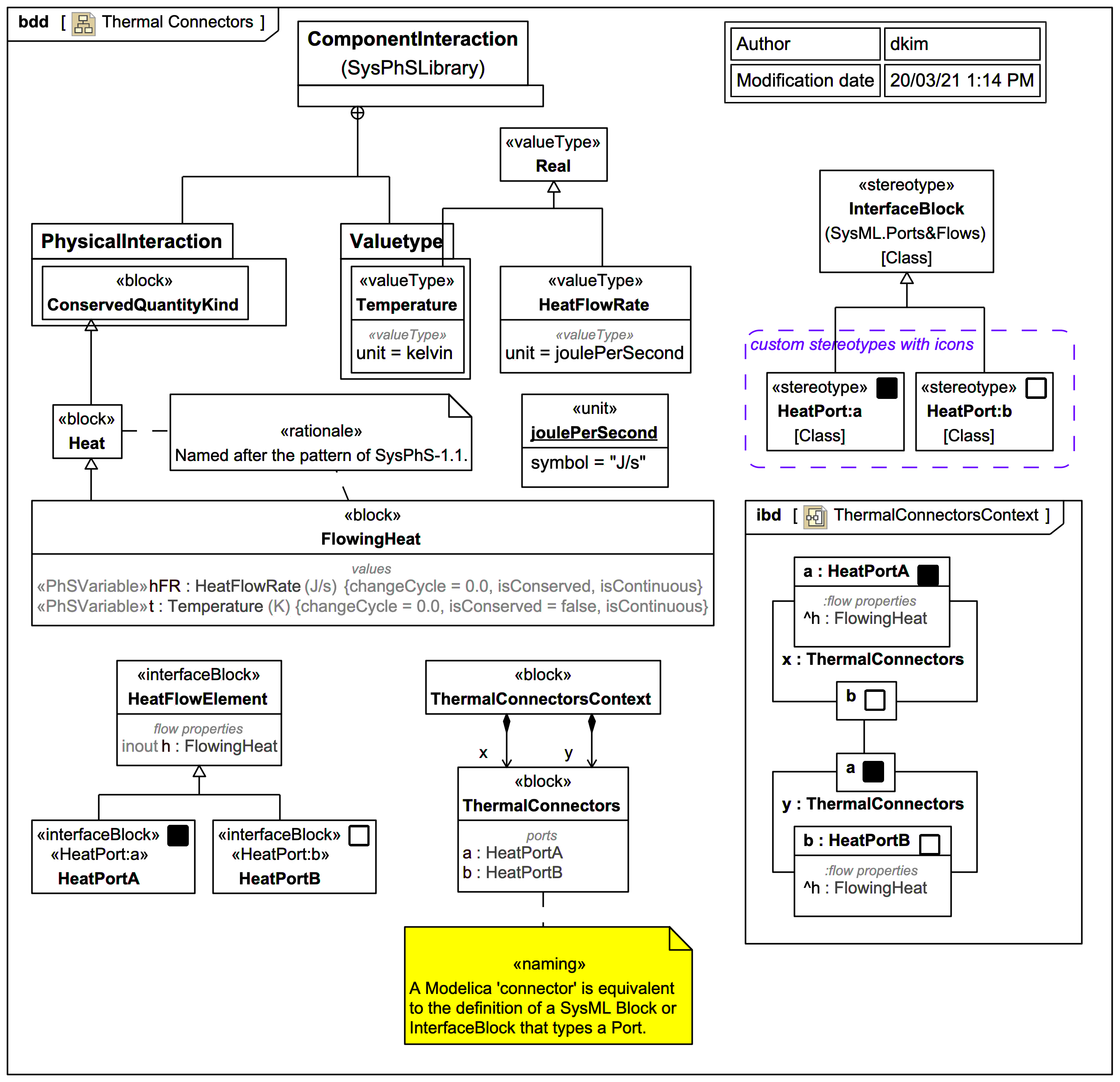
Part of the point of Modelica example is to show how one can create distinctive icons for each Modelica connector type using annotations. One can achieve something similar using custom stereotype icons.
In this SysPhS trail version the interface block HeatFlowElement from the a previous diagram is reused by inheriting into HeatPortA and HeatPortB, with corresponding custom stereotypes applied. A block ThermalConnectors has Ports types by each. The block ThermalConnectorsContext has 2 usages of ThermalConnectors with one example SysML Connector (a Modelica connect), and exports via SysPhS to Modelica as:
model ThermalConnectorsContext
  ThermalConnectorsContext _ThermalConnectorsContext;
  model ThermalConnectorsContext
    ThermalConnectors x;
    ThermalConnectors y;
  equation
    connect(x.b,y.a);
  end ThermalConnectorsContext;
  model ThermalConnectors
    HeatPortA a;
    HeatPortB b;
  end ThermalConnectors;

  connector HeatPortB
    extends HeatFlowElement;
  end HeatPortB;

  connector HeatPortA
    extends HeatFlowElement;
  end HeatPortA;

  connector HeatFlowElement
    flow HeatFlowRate hFR;
    Temperature t;
  end HeatFlowElement;

  type HeatFlowRate=Real(unit="J/s");
  type Temperature=Real(unit="K");
end ThermalConnectorsContext;
In the Internal Block Diagram (IBD) in MagicDraw/Cameo the (not so well named) Enable Parts Compartment feature has been used on the Ports, along with the option to only show the custom Stereotype icons (not the Sterotype names). The Type of the Port is only verbosely shown on the 2 non-connected Ports.