
Tags and keywords
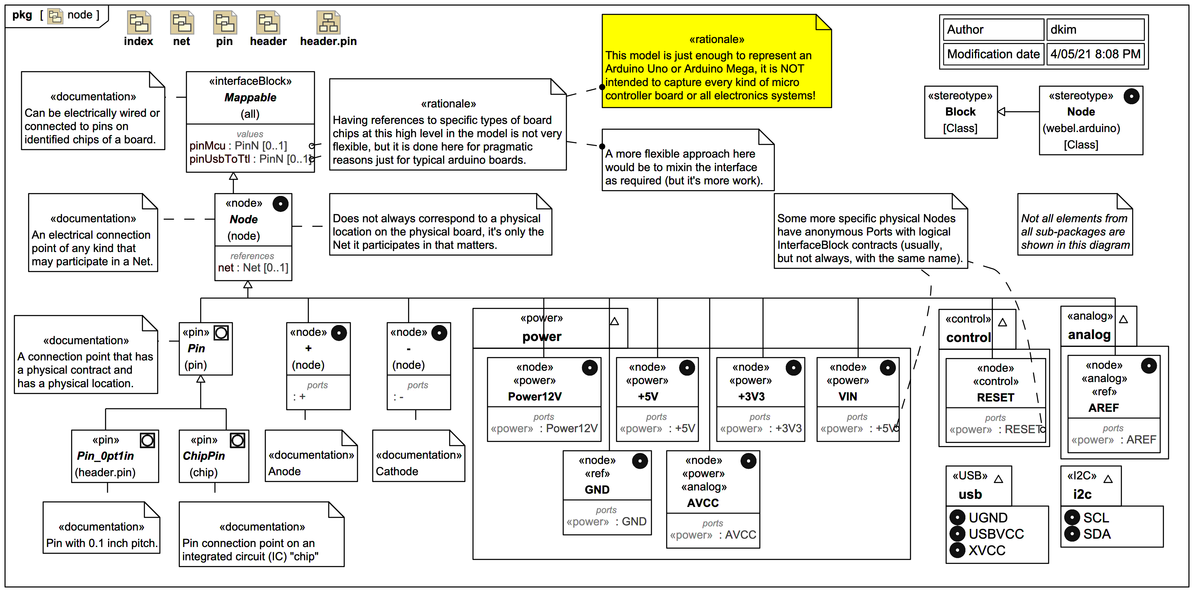
This diagram introduces the Node block and the custom «node» Stereotype, which uses MagicDraw Customizations so it acts like a new Domain Specific Language (DSL) element.
A «node» block is anything that may act as an electrical connection "point" and is part of a common voltage reference of a «net» (which we'll see next). Note, however, that in this model a «node» does not always correspond to a physical location on a board, it's only the «net» it participates in that matters.
A Node block has an optional reference to at most one «net» Net block.
A Node is abstract, and its use usually indicates that it is a placeholder for a more specific type of connection (although often there when modelling there is no compelling need to be more specific than a Node).
A Node is Mappable to pin numbers of two specific kinds of chips found on most Arduino boards, the crucial MCU microcontroller chip and the USB-to-TTL chip.
Node extend InterfaceBlock Mappable directly as shown is basically lazy inheritance organisation, it is better (but more work) to do this with mixins as needed, but it's enough to model some typical Arduino boards, noting this model is not an attempt to develop a more general electronics modelling library for SysML.Some more specific kinds of nodes are also shown:
We'll deal with the physical Pin in more detail later, for now just note it is a kind of Node with a physical connection contract (such as a physical pin type) and a location on a board.
Some of the more specific node types have anonymous Ports typed by InterfaceBlocks representing logical contracts, sometimes (but not always) with same name as the parent Node. We'll see later how this enables one to model over-loaded functionality on Pins.
There are custom stereotypes indicating various technology "layers" such as «power», «analog», «I2C», «USB», «ref» etc. Some elements may have more than one of these applied.
There are Model packages groups also roughly corresponding to technology layers, although it is not always clear (and is not critical here) which Model package a particular element is owned by.