About the aim of the trail and the SysML modelling recipe
This is not a complete beginner's Systems Modeling Language v1 (SysML®) tutorial, you'll need at least some basic SysML skills. If you want to learn SysML, refer to our online SysML tutorial trail or attend our course and learn live from the experts:
This is primarily a tutorial trail on the application of Systems Modeling Language v1 (SysML®) to modelling electronics systems rather than a tutorial about the Arduino micro-controller system. If you have some basic hobby-level electronics skills you'll do fine. Dr Darren says:I'm really not sure what's more fun, making things come to life in the real world with the wonderful Arduino microcontroller system - such as the Drancel (R,G,B) light synthesis system - or modelling electronics in SysML.Some caveats about the models shown in this trail:
- This trail does not attempt to establish a general electronics modelling library for SysML (although it could be adapted for such), it only shows how to model one specific Arduino board, and thus takes some organisational shortcuts, especially concerning the inheritance hierarchy and the packaging.
- Some of the naming is less strict than usually recommended under Webel Best Practice, such as use of special non-alpha characters like '-' and '+' in some element names, or CAPITALISED names taken from electronic component part numbers.
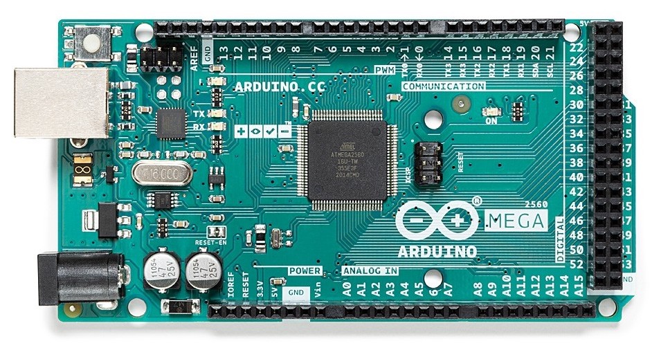
Official photograph from top above
From the Arduino store:
The Arduino online Interactive Board Viewer
The official Arduino page for the Mega 2560 Rev3 not only has (under the DOCUMENTATION tab) downloads for schematics and the full pinout diagrams as a PDF (kindly offered under the Creative Commons Attribution 4.0 International licence), it has a completely awesome online Interactive Board Viewer that synchronises between a Schematic (SCH) view, a Printed Circuit Board (PCB) view, and a 3D view. Click on nearly anything in any view and it will be highlighted in the other views, along with data and info about the component identifiers and manufacturer's part numbers.
In particular, make sure you've got the hang of the interactive net highlighting system that appears if you click more than once on a pin/pad in the SCH or 3D views. For example, you can show the entire +5V, GND, +3V3, PWRIN, and VIN nets. It might take a bit of practice at first (it can be a bit fiddly).
We'll be using the names of those nets throughout this trail model, and we'll be looking at various ways of including that information in Internal Block Diagrams in SysML1.6+ (and we'll even see how SysMLv2 promises to make this a bit easier).
Some terminology and definitions
We'll be discussing each of these also later in more detail as we use them:
- A
«net»block: A connection region with a common voltage (assuming that all electrical wiring or other connections are completely ideal and lossless with zero resistance). - A
«node»block: Anything that may act as an electrical connection "point" and is part of a common voltage reference of a «net». Note, however, that in this model a «node» does not always correspond to a physical location on the physical board, it's only the «net» it participates in that matters. - A
«pin»block: A «node» with a physical connection contract. For example, a 0.1" pitch header pin is a special case of «pin». An IC "chip" pin/pad is a special case of «pin». In most cases, the specifics of the physical connection contract are not modelled (so it matters little here whether one is dealing with a female or male header pin). A «pin» DOES always correspond with something that has a physical location on the board.
A «node» block (and thus a «pin») may (but need not) be used as the type of a Port. Only standard Ports are used here (and there is no benefit in using the more specific SysML ProxyPort or SysML FullPort at this stage of the modelling).
A «node» (and thus a «pin») may additionally have logical contracts modelled here as Ports typed by InterfaceBlocks. Often these logical contract Ports are typed by InterfaceBlocks with the same name as the Type of their owners (but packaged elsewhere). For example, a «node» GND may have a logical contract Port :GND typed by an InterfaceBlock GND. A «node» may have more than one logical contract Port. If a parent «node» is used as the type of a Port any logical contract(s) will appear as nested Ports.
The raison d'être for the logical contract Ports is that in Arduino (and on the Atmel/Microchip AVR ICs) a single pin is often used for more than one function.
Mostly in this trail we'll only be "electrically" wiring up the nodes/pins, we won't yet be connecting up their logical contracts (to express specific functionality), but it's important to know that the SysML model can easily handle this overloading of pin functionality.
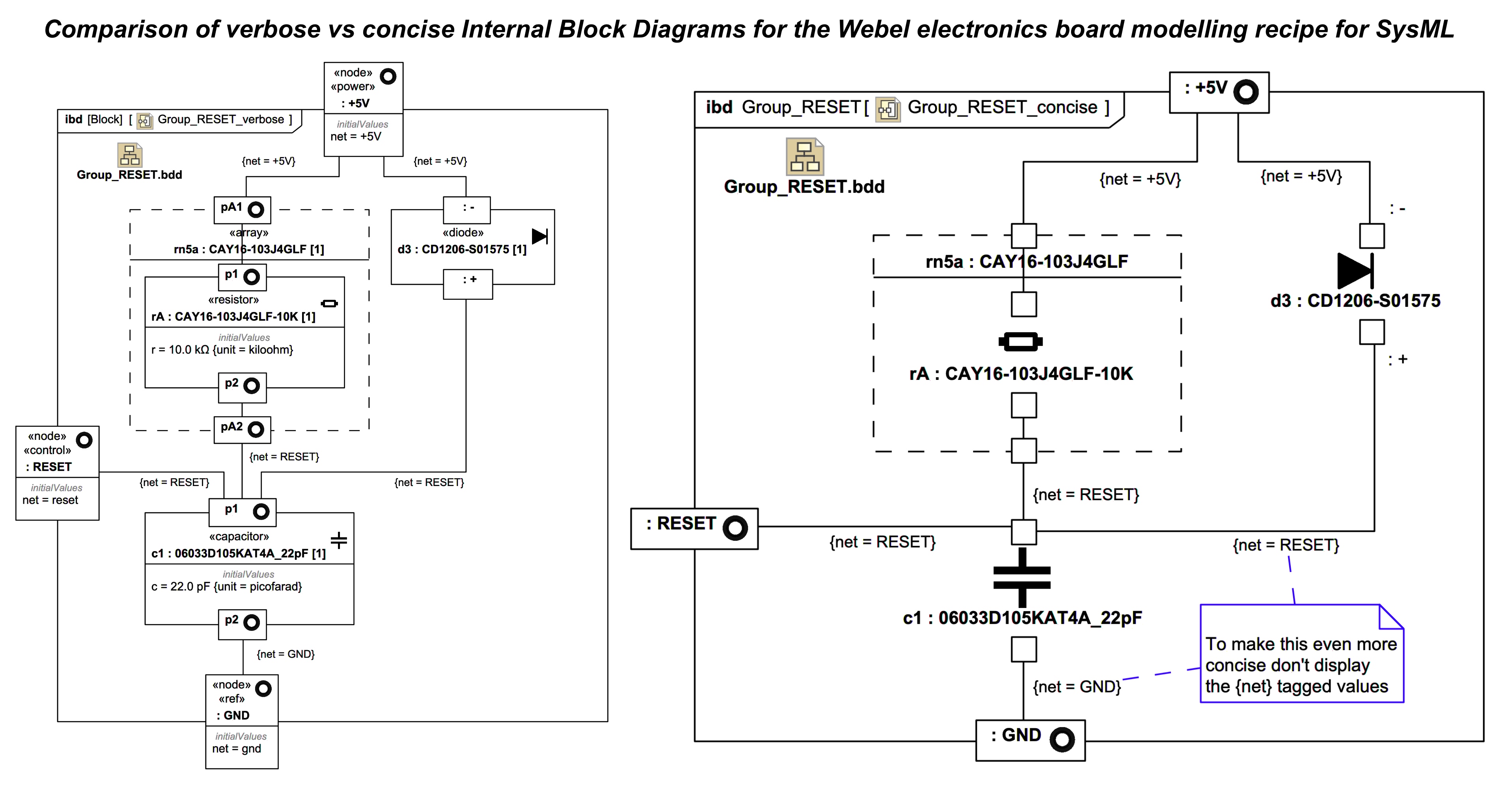
Verbose vs concise electronics modelling style
Most of the diagrams in here deliberately expose quite a lot of information (so you can see exactly what's going on in this trail). Once you've got the hang of the main modelling patterns, you can get away with hiding a lot of that information in most diagrams to give a far more concise style. You can, for example, often just display the symbol shape for stereotyped elements with icons to get nice electronics symbols, and you can even often hide the type and name from most pin or node Ports (such as those on simple 2-pin components like resistors).
This tutorial trail is composed of cross-referenced sections, a mandatory introduction that demonstrates the basic board modelling recipe, then sections that illustrate the recipe applied to aspects of the board such as power and reset (which sections have less commentary about the modelling recipe).
Learn SysML for MBSE with a Webel IT Australia Live Online web seminar or On-Site course!