
Tags and keywords
Modelling and style
A quick word on using colours. The usual Webel Best Practice is to use b/w only wherever possible and only use colours to highlight special states (like red for error, orange for warning etc.). Unless colours are associated with a per-stereotype tool style or use, for example, the MagicDraw legend system they can quickly become very difficult to manage. Most of the later (deeper) Internal Block Diagrams do not use the colours shown.
To keep things a bit compact, the DSL stereotypes «pin» and «node» are not shown here, but their icons are:
Also, the multiplicities are not shown on the Ports or net nodes (and are assumed to be 1).
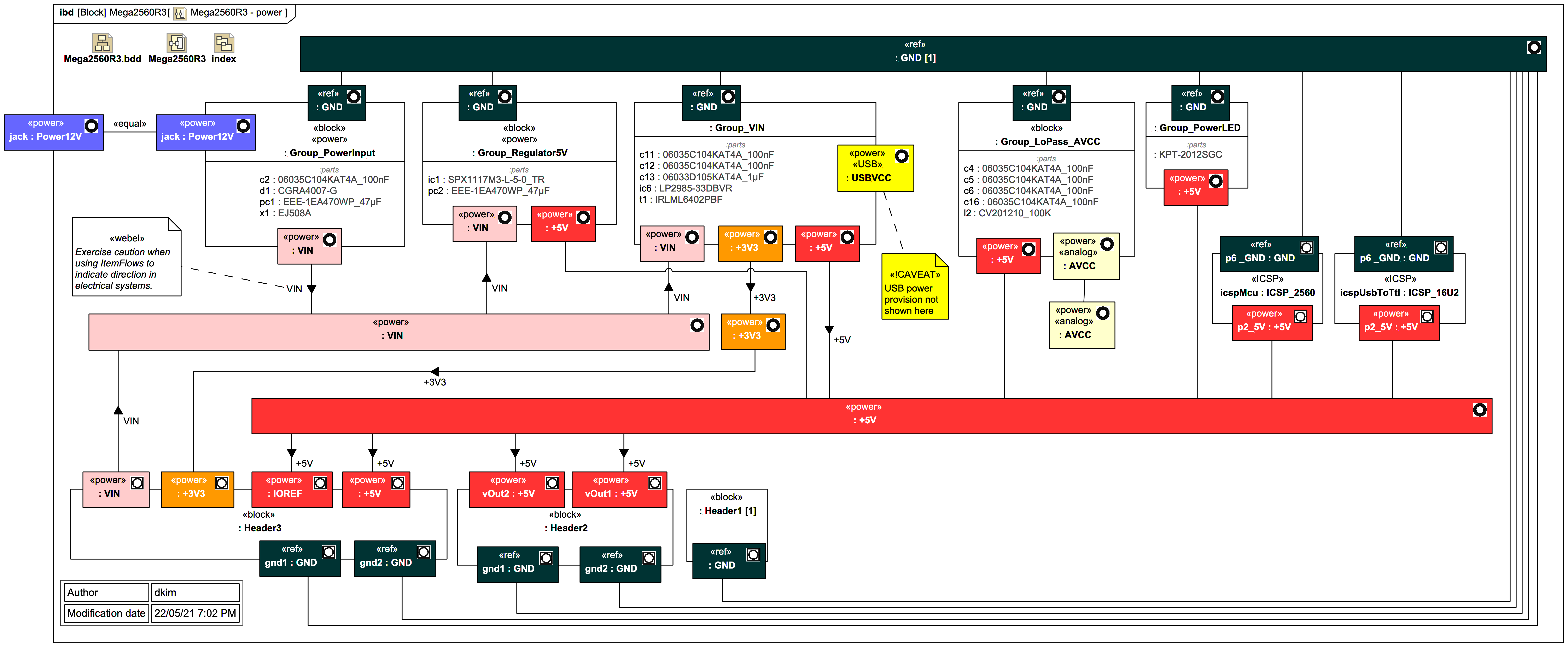
:GND bus at both the top and bottom for easier wiring, but this is not supported in SysML:
Some Connectors have classifier-level ItemFlows assigned. Great care has to be used with such ItemFlows when dealing with electrical circuits, because the actual flow direction can often depend on the state of the system. Here they have been used to indicate the general "provision" of voltage.
Also, MagicDraw/Cameo 19SP3 had some strange bugs where the ItemFlow direction sometimes flipped (supposed to be addressed in 2021x).
:Header3We're going to work through these groups from left to right to learn more about how the basic Webel electronics modelling pattern for SysML works.