
Tags and keywords
The SysMLv2 and KerML machinery in 3D in Blender using Blender Geometry Nodes!
This is one of those things that's much easier to see and understand if you interact with it live in the 3D tool.
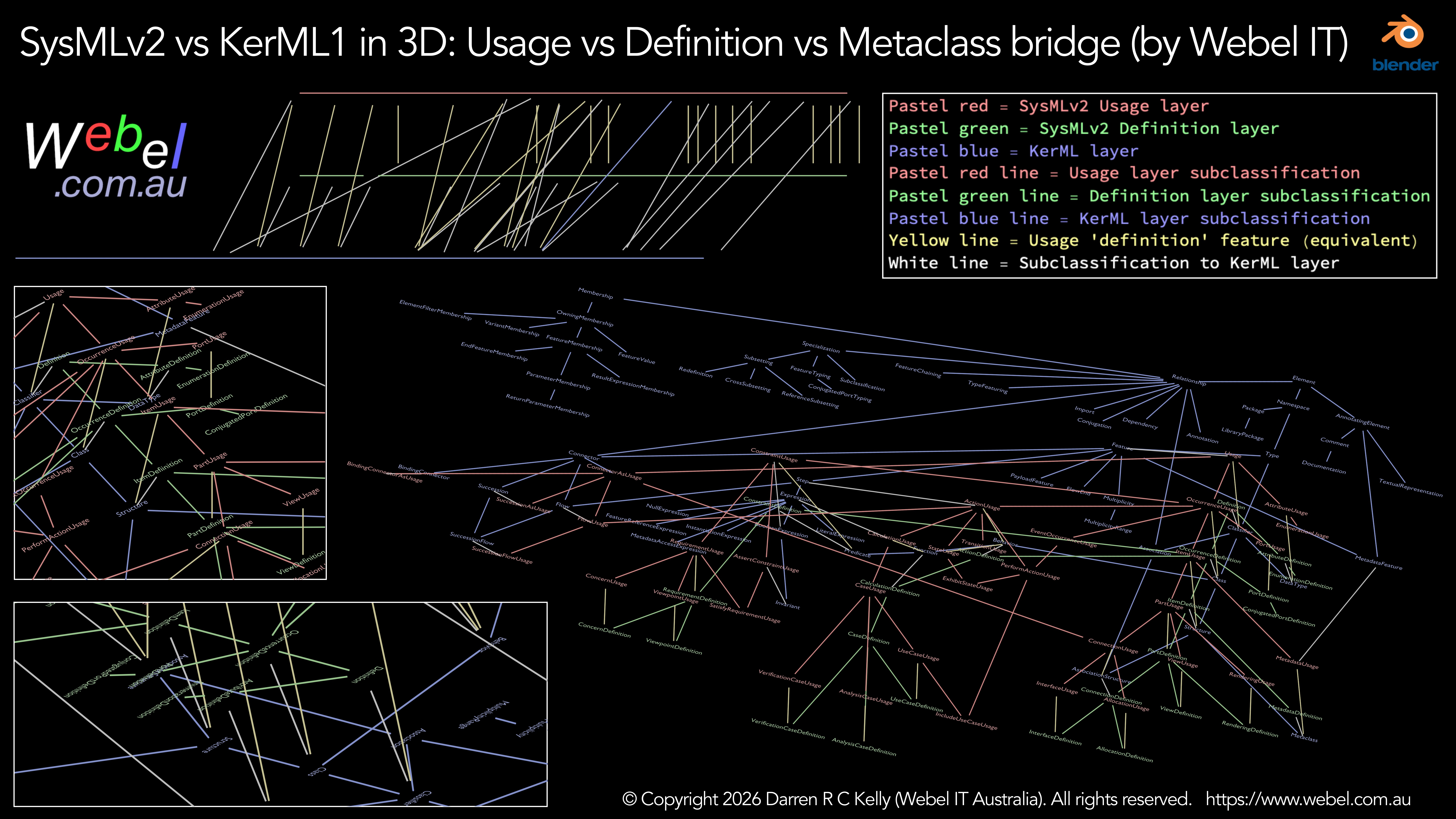
Update: Now as screencast video too:The idea is to show how the SysMLv2 Usage vs Definition system works in a way that a 2D representation can't. Selected SysMLv2 Usage level "metamodel" elements are in the top layer in pastel red. Corresponding SysMLv2 Definition level elements are below them with wires in yellow representing the corresponding 'definition' feature (or redefined equivalent) except for some special cases that bridge directly to KerML. Then at the bottom there's most of the main KerML metaclasses. White wires represent subclassifications from Usage or Definition level elements down to KerML. All other wires are subclassifications in the corresponding colour of their layer.