
Tags and keywords
The Modelica By Example target code is:
connector PositivePin "Positive pin of an electric component"
  Modelica.SIunits.Voltage v "Potential at the pin";
  flow Modelica.SIunits.Current i "Current flowing into the pin";
end PositivePin;
connector NegativePin "Negative pin of an electric component"
  Modelica.SIunits.Voltage v "Potential at the pin";
  flow Modelica.SIunits.Current i "Current flowing into the pin";
end NegativePin;
within ModelicaByExample.Components.Electrical.DryApproach;
partial model TwoPin "Common elements of two pin electrical components"
  Modelica.Electrical.Analog.Interfaces.PositivePin p
    annotation ...
  Modelica.Electrical.Analog.Interfaces.NegativePin n
    annotation ...

  Modelica.SIunits.Voltage v = p.v-n.v;
  Modelica.SIunits.Current i = p.i;
equation
  p.i + n.i = 0 "Conservation of charge";
end TwoPin;
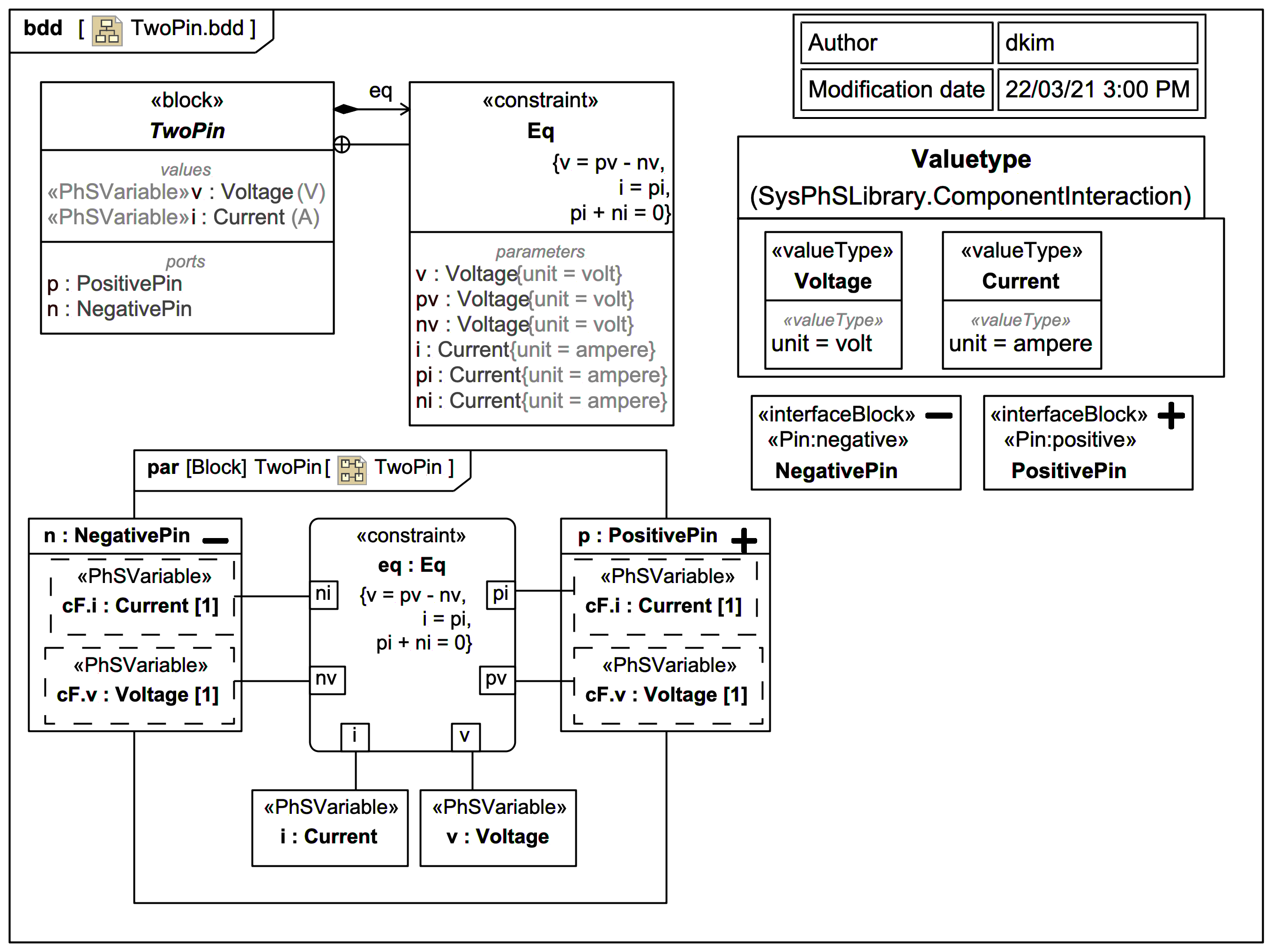
This SysML/SysPhS trail version handles the inline equations on v and i through explicit additional Constraints. It also reuses the pin definitions with custom stereotype icons from this previous slide.
The exported Modelica code is:
model TwoPin
  TwoPin _TwoPin;
  model TwoPin
    PositivePin p;
    NegativePin n;
    Voltage v;
    Current i;
  equation
    v=p.v-n.v;
    i=p.i;
    p.i+n.i=0;
  end TwoPin;
  connector PositivePin
    extends ChargeFlowElement;
  end PositivePin;
  connector NegativePin
    extends ChargeFlowElement;
  end NegativePin;
  type Voltage=Real(unit="V");
  type Current=Real(unit="A");
  connector ChargeFlowElement
    flow Current i;
    Voltage v;
  end ChargeFlowElement;
end TwoPin;