SysMLv1 Parametric Diagram of the Effectiveness-NTU Method for a finned tube cross flow air conditioner heat exchanger Gallery Tutorial [TECHNICAL SLIDE TRAIL] The Webel libraries for Wolfram Mathematica: With SysMLv1 models. Section SECTION: Miscellaneous examples of applications of Webel libraries for Mathematica to air conditioners and heat exchangers. With SysMLv1 models. Slide kind SysML Parametric Diagram
Webel: SysML4Mathematica: Does every bit of the Mathematica code need to be modelled in SysML? No. Typically just the main function parameters and their interdependencies, data structures, and main code logic. Except for special or educational purposes.
Webel: SysML4Mathematica: POLICY: Handle flow sign changes via a single negative (not duplicated and "adjusted" algebra). This strategy may come at a very slight performance cost (for benefit of more robustness).
Cameo Simulation Toolkit: You can use Mathematica as an external maths engine to share maths between an OpaqueBehavior and a ConstraintBlock using custom auto-loaded Mathematica functions (keeps a project nice and DRY and respects Single Source of Truth)
HOWTO: MagicDraw/Cameo: v2022Refresh1: JDK 11 download compatible with the modelling tools AND Apple Silicon (ARM) machines (such as M1 Max)
SysMLv1.x: Limitation: The 'body' (maths formula) of an OpaqueBehavior can't be synchronised (shared) with the 'constraint' of a ConstraintBlock (directly in the SysML model). Can lead to a WET (not DRY) model and breaks Single Source of Truth!
Webel: SysML4Mathematica: TIP: Representing Mathematica functions as SysML ConstraintBlocks modelled in Block Definition Diagram (BDD) overviews can really help you organise and document your Wolfram Language code on complex projects!
Webel: SysML4Mathematica: TIP: Representing Mathematica functions as SysML ConstraintBlocks modelled in SysML Parametric Diagrams and as Activities in SysML Activity Diagrams is super for analysing the dependencies between functions and their arguments!
SysML: Cameo Systems Modeler: A ValueType that does not extend Real might not always simulate correctly when used to type a constraint parameter of a ConstraintBlock (in a SysML Parametric Diagram) or to type a parameter (in a SysML Activity Diagram)!
Webel: SysML4Mathematica: Convention: A Mathematica Blank '_' (which pattern-matches any Expression) is represented by a custom SysML ValueType '_'
SysML4Mathematica: Example: Block Definition Diagram overview of ConstraintBlocks, their parameters, and ConstraintBlock usages representing lower-level Webel Psy library Psychrometrics functions and CoolProp wrapper usages Gallery Tutorial TRAIL: Air Conditioning Psychrometrics (vs CED Engineering course): Example results (only) in Mathematica and SysML using the Webel Psy package and MPsy class Section Slide kind SysML Block Definition Diagram (BDD)
Webel: SysML4Mathematica: An Association used as the Type of an argument or return is represented by a Block '<||>'. A List used as as the Type of an argument or return is represented by a Block '{}'. (Extending types may adapt the notation.)
TIP: Webel: SysML/UML: On the boundary of symbols for ConstraintParameters on a ConstraintProperty (ConstraintBlock usage) symbol in Parametric Diagrams use any placement or "ordering" of ConstraintParameter symbols that works for the diagram!
Webel: SysML4Mathematica: Cameo Systems Modeler: Can perform calculations with a custom Quantity ValueType (for Mathematica) directly, but DOES NOT perform units-aware algebra (no automatic conversions)
Webel: SysML4Mathematica: An '@' prefix in the name of a Block indicates a data structure (such as an Association or List) that does not have a corresponding MTools class or a Webel Abstract Data Type (ADT) "pseudo class" in the Wolfram Language code.
Webel: SysML4Mathematica: An '@' prefix in the name of a ConstraintBlock, Activity, or OpaqueBehavior indicates that it is a "@pseudo" function not represented directly in the Wolfram Language or Webel code libraries (typically for minor maths or logic)
SysML Parametrics: You can use custom stereotypes keywords «i» and «o» on constraint parameters to indicate their intended use (causality) as (i)nputs and (o)utputs on ConstraintBlocks
GOTCHA/BUG: Cameo Simulation Toolkit v2021xR1 + Mathematica: Delegation to Mathematica from ConstraintBlocks FAILS if any of the input or output parameters are larger than 99999 because they get interpreted as 1.0e5 and that trips something! Aarrrggggh!
HOWTO access custom (user-defined) Mathematica functions using Mathematica v13.2 as an external maths engine for SysML Parametrics (ConstraintBlocks) in Magic Model Analyst (Cameo Simulation Toolkit) versions 2021x, 2021xR1, 2022xR1
Mathematica + Magic Model Analyst (Cameo Simulation Toolkit) for SysML Parametrics: GOTCHA: You must use a regular '=' on the SysML side, not the Mathematica '==' (or it will be intepreted as a constraint condition to test, not an equation to solve).
HOWTO use Mathematica v12.3.2 as an external maths engine for SysML Parametrics (ConstraintBlocks) in Magic Model Analyst (Cameo Simulation Toolkit) versions 2021x, 2021xR1, 2022xR1
Interaction - Predation Gallery Tutorial TRAIL: SysML+SysPhS vs Modelica By Example in MagicDraw/Cameo SysML [tested with the Wolfram SystemsModeler for Modelica] Section 07. Components [MOST] Slide kind hybrid diagram SysML Block Definition Diagram (BDD) SysML Parametric Diagram
SinkOrSource - Reproduction - Starvation Gallery Tutorial TRAIL: SysML+SysPhS vs Modelica By Example in MagicDraw/Cameo SysML [tested with the Wolfram SystemsModeler for Modelica] Section 07. Components [MOST] Slide kind hybrid diagram SysML Block Definition Diagram (BDD) SysML Parametric Diagram
UngroundedGearComparison - comparison Gallery Tutorial TRAIL: SysML+SysPhS vs Modelica By Example in MagicDraw/Cameo SysML [tested with the Wolfram SystemsModeler for Modelica] Section 07. Components [MOST] Slide kind hybrid diagram SysML Block Definition Diagram (BDD) SysML Internal Block Diagram (IBD) SysML Parametric Diagram
GroundedGear - comparison Gallery Tutorial TRAIL: SysML+SysPhS vs Modelica By Example in MagicDraw/Cameo SysML [tested with the Wolfram SystemsModeler for Modelica] Section 07. Components [MOST] Slide kind hybrid diagram SysML Block Definition Diagram (BDD) SysML Internal Block Diagram (IBD) SysML Parametric Diagram
SMD_WithBacklash Gallery Tutorial TRAIL: SysML+SysPhS vs Modelica By Example in MagicDraw/Cameo SysML [tested with the Wolfram SystemsModeler for Modelica] Section 07. Components [MOST] Slide kind hybrid diagram SysML Block Definition Diagram (BDD) SysML Internal Block Diagram (IBD) SysML Parametric Diagram
SMD Gallery Tutorial TRAIL: SysML+SysPhS vs Modelica By Example in MagicDraw/Cameo SysML [tested with the Wolfram SystemsModeler for Modelica] Section 07. Components [MOST] Slide kind hybrid diagram SysML Block Definition Diagram (BDD) SysML Internal Block Diagram (IBD)
Compliant - RotationalInertia - Spring - Damper - Ground Gallery Tutorial TRAIL: SysML+SysPhS vs Modelica By Example in MagicDraw/Cameo SysML [tested with the Wolfram SystemsModeler for Modelica] Section 07. Components [MOST] Slide kind SysML Block Definition Diagram (BDD)
Basic Rotational Components - TwoFlange Gallery Tutorial TRAIL: SysML+SysPhS vs Modelica By Example in MagicDraw/Cameo SysML [tested with the Wolfram SystemsModeler for Modelica] Section 07. Components [MOST] Slide kind SysML Block Definition Diagram (BDD)
TwoPin - SwitchedRLC Gallery Tutorial TRAIL: SysML+SysPhS vs Modelica By Example in MagicDraw/Cameo SysML [tested with the Wolfram SystemsModeler for Modelica] Section 07. Components [MOST] Slide kind hybrid diagram SysML Block Definition Diagram (BDD)
Resistor - Capacitor - Inductor - StepVoltage - Ground Gallery Tutorial TRAIL: SysML+SysPhS vs Modelica By Example in MagicDraw/Cameo SysML [tested with the Wolfram SystemsModeler for Modelica] Section 07. Components [MOST] Slide kind hybrid diagram SysML Block Definition Diagram (BDD)
Electrical Components - TwoPin Gallery Tutorial TRAIL: SysML+SysPhS vs Modelica By Example in MagicDraw/Cameo SysML [tested with the Wolfram SystemsModeler for Modelica] Section 07. Components [MOST] Slide kind hybrid diagram SysML Block Definition Diagram (BDD) SysML Parametric Diagram
Hysteresis - ChatteringControl Gallery Tutorial TRAIL: SysML+SysPhS vs Modelica By Example in MagicDraw/Cameo SysML [tested with the Wolfram SystemsModeler for Modelica] Section 02. Discrete Behavior Slide kind hybrid diagram plot SysML Block Definition Diagram (BDD) SysML Parametric Diagram
MagicDraw/Cameo v19SP3+SysPhS-1.1: On export to Modelica sometimes repeats parts of an equation into an extending model.
Speed Measurement - SampleAndHold Gallery Tutorial TRAIL: SysML+SysPhS vs Modelica By Example in MagicDraw/Cameo SysML [tested with the Wolfram SystemsModeler for Modelica] Section 02. Discrete Behavior Slide kind hybrid diagram plot SysML Block Definition Diagram (BDD) SysML Parametric Diagram
Switched RLC Circuit - SwitchedRLC Gallery Tutorial TRAIL: SysML+SysPhS vs Modelica By Example in MagicDraw/Cameo SysML [tested with the Wolfram SystemsModeler for Modelica] Section 02. Discrete Behavior Slide kind hybrid diagram plot SysML Block Definition Diagram (BDD) SysML Parametric Diagram
State Event Handling - Decay1 Gallery Tutorial TRAIL: SysML+SysPhS vs Modelica By Example in MagicDraw/Cameo SysML [tested with the Wolfram SystemsModeler for Modelica] Section 02. Discrete Behavior Slide kind hybrid diagram plot SysML Block Definition Diagram (BDD) SysML Parametric Diagram
Bouncing Ball Gallery Tutorial TRAIL: SysML+SysPhS vs Modelica By Example in MagicDraw/Cameo SysML [tested with the Wolfram SystemsModeler for Modelica] Section 02. Discrete Behavior Slide kind hybrid diagram plot SysML Block Definition Diagram (BDD) SysML Parametric Diagram
Cooling Revisited - NewtonCoolingSteadyThenDynamic Gallery Tutorial TRAIL: SysML+SysPhS vs Modelica By Example in MagicDraw/Cameo SysML [tested with the Wolfram SystemsModeler for Modelica] Section 02. Discrete Behavior Slide kind hybrid diagram plot SysML Block Definition Diagram (BDD) SysML Parametric Diagram
Cooling Revisited - NewtonCoolingDynamic Gallery Tutorial TRAIL: SysML+SysPhS vs Modelica By Example in MagicDraw/Cameo SysML [tested with the Wolfram SystemsModeler for Modelica] Section 02. Discrete Behavior Slide kind hybrid diagram plot SysML Block Definition Diagram (BDD) SysML Parametric Diagram
Lotka-Volterra Systems - QuiescentModelWithModifications Gallery Tutorial TRAIL: SysML+SysPhS vs Modelica By Example in MagicDraw/Cameo SysML [tested with the Wolfram SystemsModeler for Modelica] Section 01. Basic Equations Slide kind hybrid diagram plot SysML Block Definition Diagram (BDD) SysML Parametric Diagram
Lotka-Volterra Systems - QuiescentModelUsingStart Gallery Tutorial TRAIL: SysML+SysPhS vs Modelica By Example in MagicDraw/Cameo SysML [tested with the Wolfram SystemsModeler for Modelica] Section 01. Basic Equations Slide kind hybrid diagram plot SysML Block Definition Diagram (BDD) SysML Parametric Diagram
Lotka-Volterra Systems - ClassicModel Gallery Tutorial TRAIL: SysML+SysPhS vs Modelica By Example in MagicDraw/Cameo SysML [tested with the Wolfram SystemsModeler for Modelica] Section 01. Basic Equations Slide kind hybrid diagram plot SysML Block Definition Diagram (BDD) SysML Parametric Diagram
A Mechanical Example - SecondOrderSystem Gallery Tutorial TRAIL: SysML+SysPhS vs Modelica By Example in MagicDraw/Cameo SysML [tested with the Wolfram SystemsModeler for Modelica] Section 01. Basic Equations Slide kind hybrid diagram plot SysML Block Definition Diagram (BDD) SysML Parametric Diagram
An Electrical Example - RLC1 Gallery Tutorial TRAIL: SysML+SysPhS vs Modelica By Example in MagicDraw/Cameo SysML [tested with the Wolfram SystemsModeler for Modelica] Section 01. Basic Equations Slide kind hybrid diagram plot SysML Block Definition Diagram (BDD) SysML Parametric Diagram
Getting Physical - NewtonCoolingWithTypes Gallery Tutorial TRAIL: SysML+SysPhS vs Modelica By Example in MagicDraw/Cameo SysML [tested with the Wolfram SystemsModeler for Modelica] Section 01. Basic Equations Slide kind hybrid diagram plot SysML Block Definition Diagram (BDD) SysML Parametric Diagram
Getting Physical - NewtonCoolingWithDefaults Gallery Tutorial TRAIL: SysML+SysPhS vs Modelica By Example in MagicDraw/Cameo SysML [tested with the Wolfram SystemsModeler for Modelica] Section 01. Basic Equations Slide kind hybrid diagram plot SysML Block Definition Diagram (BDD) SysML Parametric Diagram
Simple First Order System - FirstOrderSteady Gallery Tutorial TRAIL: SysML+SysPhS vs Modelica By Example in MagicDraw/Cameo SysML [tested with the Wolfram SystemsModeler for Modelica] Section 01. Basic Equations Slide kind hybrid diagram plot SysML Block Definition Diagram (BDD) SysML Parametric Diagram
Simple First Order System - FirstOrderInitial Gallery Tutorial TRAIL: SysML+SysPhS vs Modelica By Example in MagicDraw/Cameo SysML [tested with the Wolfram SystemsModeler for Modelica] Section 01. Basic Equations Slide kind hybrid diagram plot SysML Block Definition Diagram (BDD) SysML Parametric Diagram
Simple First Order System - FirstOrder Gallery Tutorial TRAIL: SysML+SysPhS vs Modelica By Example in MagicDraw/Cameo SysML [tested with the Wolfram SystemsModeler for Modelica] Section 01. Basic Equations Slide kind hybrid diagram plot SysML Block Definition Diagram (BDD) SysML Parametric Diagram
MagicDraw/Cameo: SysML Parametrics: To colour instance table cells to indicate broken constraints you need to create at least one Simulation Configuration Diagram, which loads a validation profile with colour coding rules.
BDD & PD: EvaporationCalculation2 Gallery Tutorial TRAIL: SysPhS-1.1 Annex A examples in MagicDraw/Cameo SysML vs Modelica (Wolfram SystemsModeler) Section Annex A.5: Humidifier (with Units) Slide kind hybrid diagram SysML Block Definition Diagram (BDD) SysML Parametric Diagram
BDD & PD: EvaporationCalculation Gallery Tutorial TRAIL: SysPhS-1.1 Annex A examples in MagicDraw/Cameo SysML vs Modelica (Wolfram SystemsModeler) Section Annex A.5: Humidifier (with Units) Slide kind hybrid diagram SysML Block Definition Diagram (BDD) SysML Parametric Diagram
BDD & PD: TemperatureIncrease Gallery Tutorial TRAIL: SysPhS-1.1 Annex A examples in MagicDraw/Cameo SysML vs Modelica (Wolfram SystemsModeler) Section Annex A.5: Humidifier (with Units) Slide kind hybrid diagram SysML Block Definition Diagram (BDD) SysML Parametric Diagram
BDD & PD: VaporGenerationPlantCalculation Gallery Tutorial TRAIL: SysPhS-1.1 Annex A examples in MagicDraw/Cameo SysML vs Modelica (Wolfram SystemsModeler) Section Annex A.5: Humidifier (with Units) Slide kind hybrid diagram SysML Block Definition Diagram (BDD) SysML Parametric Diagram
BDD & PD: Radiation Gallery Tutorial TRAIL: SysPhS-1.1 Annex A examples in MagicDraw/Cameo SysML vs Modelica (Wolfram SystemsModeler) Section Annex A.5: Humidifier (with Units) Slide kind hybrid diagram SysML Block Definition Diagram (BDD) SysML Parametric Diagram
Webel vs SysPhS-1.1: Annex A.5: Humidifier: In the Webel version it will be tentatively assumed we are in fact dealing with a large humidified space like an office building NOT a single "humidified room" - despite the block name HumidifiedRoom in the spec
Webel vs SysPhS-1.1: Annex A.5: Humidifier: If the WaterTank::tankVolume 50,000 is measured in litres (L) the VaporPressureCalculation::volume within the HumidifiedRoom can't possibly be 25000.0 litre (L), it has to be 25000.0 (m^3), which is NOT a "room"
Webel vs SysPhS-1.1: Annex A.5: Humidifier: It is assumed that 'HumidityBalance::volume = 25,000' and 'VaporPressureCalculation::volume = 25,000' are the same fixed SpaceVolume in cubic metres (m^3).
Webel vs SysPhS-1.1: Annex A.5: Humidifier: Dimensional analysis of VaporPressureCalculationConstraint implies each 1 mL of water is equated with EXACTLY 1 g of produced vapor.
Webel vs SysPhS-1.1: Annex A.5: Humidifier: Dimensional analysis of VaporPressureCalculationConstraint implies the output is a pressure rate, which makes no sense as consumed by RelativeHumidityCalculation and is inconsistent with the rest of the system.
Webel vs SysPhS-1.1: Annex A.5: Humidifier: Dimensional analysis of HumidityBalanceConstraint implies constraint parameter 'airExRate' in {change=((humidity-envH)*(volume*airExRate))} is per-volume, assuming that 'volume' is a fixed Volume.
Webel vs SysPhS-1.1: Annex A.5: Humidifier: Dimensional analysis of RelativeHumidityCalculationConstraint implies constraint parameter 'change' in {der(x)=((press/satVap)-change)/c2} is a unitless relative humidity, given that 'c2' is a Time.
BDD & PD: VolumeConversion Gallery Tutorial TRAIL: SysPhS-1.1 Annex A examples in MagicDraw/Cameo SysML vs Modelica (Wolfram SystemsModeler) Section Annex A.5: Humidifier (with Units) Slide kind hybrid diagram SysML Block Definition Diagram (BDD) SysML Parametric Diagram
SysPhS-1.1: p.81: 'resistance:ViscousResistance' (in Figure 60) has to be treated as a PhSVariable not a PhSConstant, otherwise get an invalid system with 6 variables and 7 equations.
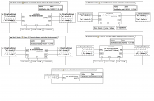
Parametric diagrams: Figure 62, Figure 63 Gallery Tutorial TRAIL: SysPhS-1.1 Annex A examples in MagicDraw/Cameo SysML vs Modelica (Wolfram SystemsModeler) Section Annex A.4: Hydraulics Slide kind hybrid diagram SysML Parametric Diagram
Figure 62 and Figure 63 show the parametric diagrams of the tank and the pipe, respectively. Source SysPhS-1.1
Binding connectors link constraint parameters to simulation variables and constants, indicating their values must be the same. Source SysPhS-1.1
Component parametric diagrams show properties typed by constraint blocks (constraint properties), as well as component and port simulation variables and constants. Source SysPhS-1.1
Equations in constraint blocks are applied to components using binding connectors in component parametric diagrams. Source SysPhS-1.1
Also, the fluid flow in the tank, fluidFlow, is related to the change in the fluid height level fluidHeight over time and the cross-sectional surface area of the tank, surfaceArea. Source SysPhS-1.1
The tank constraints specify that the pressure in the tank, pressure depends on the height of the fluid level in the tank, fluidHeight, as well as properties of the fluid, fluidDensity. Source SysPhS-1.1
The sum of the fluid flow rates going through the two pipe openings is zero (the fluid is assumed to be incompressible). Source SysPhS-1.1
The magnitude of fluid flow rate through the pipe fluidFlow is the same as the magnitude of flow rates opening1FluidFlow and opening2FluidFlow going through the pipe’s openings, though the values differ in sign. Source SysPhS-1.1
The fluid flow rate through the pipe, fluidFlow, is proportional to the pressure difference by the constant resistance, which depends on the geometric properties of the pipe as well as fluidic properties. Source SysPhS-1.1
The pipe constraints specify that the pressure pressureDiff across it is equal to the difference of fluid pressures opening1Pressure and opening2Pressure at each end of the pipe. Source SysPhS-1.1
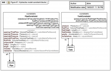
In this example, constraint blocks PipeConstraint and TankConstraint define parameters and equations for pipes and tanks, respectively, as shown in Figure 61. Source SysPhS-1.1
Equations define mathematical relationships between the values of numeric variables. Equations in SysML, are constraints in constraint blocks that use properties of the blocks (parameters) as variables. Source SysPhS-1.1
BDD: Figure 61: Hydraulics model constraint blocks Gallery Tutorial TRAIL: SysPhS-1.1 Annex A examples in MagicDraw/Cameo SysML vs Modelica (Wolfram SystemsModeler) Section Annex A.4: Hydraulics Slide kind SysML Block Definition Diagram (BDD)
Figure 52 through Figure 57 show parametric diagrams for the source, amplifier, high-pass fil[t]er, low-pass filter, mixer, and sink, respectively. Source SysPhS-1.1
Binding connectors link constraint parameters to simulation variables and constants, indicating their values must be the same. Source SysPhS-1.1
Component parametric diagrams show properties typed by constraint blocks (constraint properties), as well as component and port simulation variables and constants. Source SysPhS-1.1
Equations in constraint blocks are applied to components using binding connectors in component parametric diagrams. Source SysPhS-1.1
The source constraint specifies a sine wave signal with the parameter amp as its amplitude. The sink constraint displays (scopes) the output signal from the signal processor. Source SysPhS-1.1
The mixer constraint specifies the relationship between its one output and the two inputs that come from the low-pass and high-pass filters. The constraint defines the output to be the average of the inputs. Source SysPhS-1.1
The amplifier changes the signal strength by a factor gain, the low-pass filter eliminates the high-frequency components of the incoming signal, and the high-pass filter eliminates the low-frequency components of the signal. Source SysPhS-1.1
The amplifier, low-pass fil[t]er, and high-pass filter constraints show the input-output relationship of these components as the signal passes through them. Source SysPhS-1.1
In this example, a constraint block BinarySignalComponentConstraint defines the parameters for one input (ip) and one output (op), common to amplifiers, low-pass filters, and high-pass filters, as shown in Figure 51. Source SysPhS-1.1
Equations define mathematical relationships between the values of numeric variables. Equations in SysML, are constraints in constraint blocks that use properties of the blocks (parameters) as variables. Source SysPhS-1.1
Parametric diagrams: Figure 52, Figure 53, Figure 54, Figure 55, Figure 56, Figure 57 Gallery Tutorial TRAIL: SysPhS-1.1 Annex A examples in MagicDraw/Cameo SysML vs Modelica (Wolfram SystemsModeler) Section Annex A.3: Signal Processor Slide kind hybrid diagram SysML Parametric Diagram
The source constraint defines the voltage across it as a sine wave with the parameter amp as its amplitude. Source SysPhS-1.1
The source constraint defines the circuit’s electrical source. The ground constraint specifies that the voltage at the ground pin is zero. Source SysPhS-1.1
The constraints for the resistor, capacitor, and inductor specify the voltage/current relationship with resistance, capacitance, and inductance, respectively. Source SysPhS-1.1
The sum of the current going through the two pins adds up to zero (one is the negative of the other), because the components do not create, destroy, or store charge. Source SysPhS-1.1
The current i through the component is equal to the current going through the positive pin. Source SysPhS-1.1
These specify that the voltage v across the component is equal to the difference between the voltage at the positive and negative pins. The current i through the component is equal to the current going through the positive pin. Source SysPhS-1.1
In this example, a constraint block BinaryElectricalComponentConstraint defines parameters and constraints common to resistors, inductors, capacitors, and sources, as shown in Figure 40. Source SysPhS-1.1
Equations define mathematical relationships between the values of numeric variables. Equations in SysML, are constraints in constraint blocks that use properties of the blocks (parameters) as variables. Source SysPhS-1.1
Parametric diagrams: Figure 41, Figure 42, Figure 43, Figure 44, Figure 45 Gallery Tutorial TRAIL: SysPhS-1.1 Annex A examples in MagicDraw/Cameo SysML vs Modelica (Wolfram SystemsModeler) Section Annex A.2: Electric Circuit Slide kind hybrid diagram SysML Parametric Diagram
BDD: Figure 40: Circuit constraint blocks Gallery Tutorial TRAIL: SysPhS-1.1 Annex A examples in MagicDraw/Cameo SysML vs Modelica (Wolfram SystemsModeler) Section Annex A.2: Electric Circuit Slide kind SysML Block Definition Diagram (BDD)
The block SpringMassSys has a SysML constraint property smsc typed by SMSConstraint. The constraint block has six parameters, each bound to a property reachable from the spring mass system: Source SysPhS-1.1
Figure 25 shows an example [USAGE OF A] constraint block for a signal flow application, using ports like those defined in Figure 22, Subclause 10.7.3, except in a system containing a spring attached to another object. Source SysPhS-1.1
SysML: HOWTO Safely incorporate ConstraintBlock equations from a library into a project with local ValueType variants: CASE: SysPhS vs ISO-80000 ModelLibrary
f1 is replaced by p1.f, v1 is replaced by p1.lV, x is replaced by lengthchg, k is replaced by springcst, v is replaced by velocitydiff, f is replaced by forcethru, v2 is replaced by p2.v, and f2 is replaced by p2.f. Source SysPhS-1.1
The following Modelica code corresponds to Figure 26. It has five equations from the SysML constraint block. SysML parameter names are replaced in the Modelica equations according the bindings in Figure 14 [ERROR]: Source SysPhS-1.1
(and flow properties in SysML property paths leading to PhSVariables on conserved quantity kinds are omitted in Modelica, see Subclause 10.7.8). Source SysPhS-1.1
In a SysML block with constraint properties, the constraints correspond to the same equations in Modelica ... except the SysML parameters in those equations correspond in Modelica to the properties they are bound to in SysML Source SysPhS-1.1
Figure 26: Constraint block for physical interaction in SysML Gallery Tutorial TRAIL: SysPhS-1.1 specification body figures in MagicDraw/Cameo SysML vs Modelica [using Wolfram SystemsModeler] Section Slide kind hybrid diagram SysML Block Definition Diagram (BDD) SysML Parametric Diagram
SysML parameter names are replaced in the Modelica equations according to the bindings in Figure 13 [ERROR]: f is replaced by u, pos is replaced by y, x is replaced by position, k is replaced by springcst, v is replaced by velocity, m is replaced by mass. Source SysPhS-1.1
The following Modelica code corresponds to Figure 25. It has three equations from the constraint block. Source SysPhS-1.1
In a SysML block with constraint properties, the constraints correspond to the same equations in Modelica ... except the SysML parameters in those constraints correspond in Modelica to the properties they are bound to in SysML. Source SysPhS-1.1
Figure 25: Constraint block for signal flow in SysML Gallery Tutorial TRAIL: SysPhS-1.1 specification body figures in MagicDraw/Cameo SysML vs Modelica [using Wolfram SystemsModeler] Section Slide kind hybrid diagram SysML Block Definition Diagram (BDD) SysML Parametric Diagram
MagicDraw SysML/Cameo: GOTCHA: A Constraint created and applied to a ConstraintBlock via the sidebar menu is NOT owned by the ConstraintBlock!
Trade study with multiple targets Gallery Tutorial TRAIL: HOWTO simulate Dependency Injection of SysML Parametric calculations Section Slide kind hybrid diagram MagicDraw/Cameo: table SysML Block Definition Diagram (BDD) SysML Internal Block Diagram (IBD)
A 2nd injection target I_B Gallery Tutorial TRAIL: HOWTO simulate Dependency Injection of SysML Parametric calculations Section Slide kind hybrid diagram MagicDraw/Cameo: table SysML Block Definition Diagram (BDD) SysML Parametric Diagram table
MultiClient with two injectable service targets Gallery Tutorial TRAIL: HOWTO simulate Dependency Injection of SysML Parametric calculations Section Slide kind hybrid diagram SysML Block Definition Diagram (BDD) SysML Parametric Diagram
Trade(-off) study for Client with A1 and A2 instances (dependency injection) Gallery Tutorial TRAIL: HOWTO simulate Dependency Injection of SysML Parametric calculations Section Slide kind hybrid diagram SysML Block Definition Diagram (BDD) SysML Internal Block Diagram (IBD)
Parametric diagrams with BindingConnectors for concrete implementation blocks A1 and A2 Gallery Tutorial TRAIL: HOWTO simulate Dependency Injection of SysML Parametric calculations Section Slide kind hybrid diagram SysML Parametric Diagram
Variations on concrete implementations of I_A and the constraints with computations they carry Gallery Tutorial TRAIL: HOWTO simulate Dependency Injection of SysML Parametric calculations Section Slide kind SysML Block Definition Diagram (BDD)
The problem statement: A Client subscribes to an output value property but does not know what computes it or how Gallery Tutorial TRAIL: HOWTO simulate Dependency Injection of SysML Parametric calculations Section Slide kind hybrid diagram SysML Block Definition Diagram (BDD) SysML Parametric Diagram
TRAIL: HOWTO simulate Dependency Injection of SysML Parametric calculations Jump to first slide The problem statement: A Client subscribes to an output value property but does not know what computes it or how Sections
SysML Parametrics: You can use custom stereotypes keywords «i» and «o» to indicate value properties that are intended to be used as (i)nputs and (o)utputs when bound to constraint parameters for SysML Parametrics
Calculate wavelengths from frequencies and compare EM regions in a table Gallery Tutorial TRAIL: Webel SysML Parsing Analysis example: Optical telescopes from Wikipedia: Structure and port-based light flow model Section Slide kind hybrid diagram MagicDraw/Cameo: table SysML Package Diagram SysML Parametric Diagram
Radio frequencies (just a quick look) Gallery Tutorial TRAIL: Webel SysML Parsing Analysis example: Optical telescopes from Wikipedia: Structure and port-based light flow model Section Slide kind SysML Block Definition Diagram (BDD)
There are six types of quarks (and six antiquarks) This content has been marked as discussing an ADVANCED topic! Gallery Tutorial TRAIL: Webel SysML Parsing Analysis example: A particle physics taxonomy from Wikipedia Section Slide kind SysML Block Definition Diagram (BDD)
Converting mass and charge using SysML Parametrics Gallery Tutorial TRAIL: Webel SysML Parsing Analysis example: A particle physics taxonomy from Wikipedia Section Slide kind hybrid diagram SysML Block Definition Diagram (BDD) SysML Parametric Diagram
Focus BDD for the Lepton block Gallery Tutorial TRAIL: Webel SysML Parsing Analysis example: A particle physics taxonomy from Wikipedia Section Slide kind SysML Block Definition Diagram (BDD)
Calculate whether a specific particle is a lepton using SysML parametrics Gallery Tutorial TRAIL: Webel SysML Parsing Analysis example: A particle physics taxonomy from Wikipedia Section Slide kind SysML Parametric Diagram
Our first Parsing Analysis diagram about leptons Gallery Tutorial TRAIL: Webel SysML Parsing Analysis example: A particle physics taxonomy from Wikipedia Section Slide kind SysML Block Definition Diagram (BDD)
REFERENCE CARD: Property cheat-sheet for Block Gallery Tutorial TRAIL: Webel's ultimate guide to Systems Modeling Language (v1) with MagicDraw/Cameo Section 08:01: The building Blocks of SysML Slide kind SysML Block Definition Diagram (BDD)
The parametric diagram is a new SysML diagram type that describes the constraints among the properties associated with blocks. This diagram is used to integrate behavior and structure models with engineering analysis models such as performance, ... Source OMG Systems Modeling Language (SysML) 1.6
Constraint Properties are a special class of property used to constrain other properties of blocks... Source OMG Systems Modeling Language (SysML) 1.6
REFERENCE CARD: Types of Block Properties and Block compartments Gallery Tutorial TRAIL: Webel's ultimate guide to Systems Modeling Language (v1) with MagicDraw/Cameo Section 08:01: The building Blocks of SysML Slide kind SysML Block Definition Diagram (BDD)
MagicDraw/Cameo support for the SysML Parametric Diagram and ConstraintBlocks for equations and mathematics is excellent, and it integrates with powerful maths engines such as Mathematica. It CAN be used on industrial strength real-world projects.
The SysML Parametric Diagram and the ContraintBlock technology for equations and mathematics is clever, powerful, useful, and integrates well with the other model-based engineering aspects of SysML.
10:01: [LINKS TO EXAMPLES] ConstraintBlocks: equations, parametrics, and mathematics in SysML TRAIL: Webel's ultimate guide to Systems Modeling Language (v1) with MagicDraw/Cameo
ExampleBlock in a Block Definition Diagram (BDD) Gallery Tutorial TRAIL: Webel's ultimate guide to Systems Modeling Language (v1) with MagicDraw/Cameo Section 08:01: The building Blocks of SysML Slide kind SysML Block Definition Diagram (BDD)
MagicDraw/Cameo can parse the 'text' field of some mathematical Requirements and populate the constraint (and also then the constraint parameters) of a ConstraintBlock that refines a Requirement (your mileage varies).
parametric diagrams can make use of the nested property name notation to refer to multiple levels of nested property containment, as shown in this example. Source OMG Systems Modeling Language (SysML) 1.6
Figure D.32 shows the use of constraint properties on a parametric diagram. This diagram shows the use of nested property references to the properties of the parts; Source OMG Systems Modeling Language (SysML) 1.6
Figure 10-1: Stereotypes defined in SysML ConstraintBlocks package Gallery Tutorial TRAIL: The SysML-1.6 Hybrid SUV sample and specification diagrams in MagicDraw/Cameo (with annotations) [UNDERGOING UPDATE to SysML1.7] Section Section: SysML-1.6 specification diagrams: 10 ConstraintBlocks Slide kind UML Profile Diagram
It assumes a constant 100hp at the drive wheels, 4000lb gross vehicle weight, and constant values for Cd and Cf. Source OMG Systems Modeling Language (SysML) 1.6
For illustration purposes, however, the interaction shown in Figure D.35 was generated based on the constraints and parameters of the StraightLineVehicleDynamics constraintBlock, as described in the Figure D.33. Source OMG Systems Modeling Language (SysML) 1.6
The constraints and parameters in Figure D.33 are detailed in Figure D.34 in Block Definition Diagram format. Note the use of valueTypes [ValueTypes] originally defined in Figure D.2. Source OMG Systems Modeling Language (SysML) 1.6
Figure D.34 - Defining Straight-Line Vehicle Dynamics Mathematical Constraints (Definition of Dynamics) Gallery Tutorial TRAIL: The SysML-1.6 Hybrid SUV sample and specification diagrams in MagicDraw/Cameo (with annotations) [UNDERGOING UPDATE to SysML1.7] Section Section: SysML-1.6: HSUV sample Slide kind SysML Block Definition Diagram (BDD)
MagicDraw/Cameo: Does not support ConstraintNote: Can't callout the Constraint of the ConstraintBlock of a constraint property into a Note on a Parametric Diagram (show on the constraint property symbol instead)
The StraightLineVehicleDynamics constraint block from Figure D.32 has been expanded in Figure D.33. ConstraintNotes are used, which identify each constraint using curly brackets {}. In addition, Rationale has been used to explain the meaning ... Source OMG Systems Modeling Language (SysML) 1.6
Since overall fuel economy is a key requirement on the HSUV design, this example applies significant detail in assessing it. Figure D.32 shows the constraint blocks and properties necessary to evaluate fuel economy. Source OMG Systems Modeling Language (SysML) 1.6
SysML-1.6: Figure D.31 has constraint parameter 'vc' on ':CapacityEquation', which is inconsistent w.r.t. parameters 'V1', 'V2', 'V3' and constraint {pcap=Sum(Vi)) shown in Figure D.26.
This non-normative extension includes stereotypes for an objective function and a measure of effectiveness. The objective function is a stereotype of a ConstraintBlock and the measure of effectiveness is a stereotype of a block property. Source OMG Systems Modeling Language (SysML) 1.6
Figure D.26 - Defining Analyses for Hybrid SUV Engineering Development (Block Definition Diagram) Gallery Tutorial TRAIL: The SysML-1.6 Hybrid SUV sample and specification diagrams in MagicDraw/Cameo (with annotations) [UNDERGOING UPDATE to SysML1.7] Section Section: SysML-1.6: HSUV sample Slide kind SysML Block Definition Diagram (BDD)
Figure D.26 defines the various model elements that will be used to conduct analysis in this example. It depicts each of the constraint blocks/equations that will be used for the analysis, and key relationships between them. Source OMG Systems Modeling Language (SysML) 1.6
A parametric diagram is a restricted form of internal block diagram that shows only the use of constraint blocks along with the properties they constrain within a context. Source OMG Systems Modeling Language (SysML) 1.6
The usage of a constraint block is distinguished from other parts by a box having rounded corners rather than the square corners of an ordinary part. Source OMG Systems Modeling Language (SysML) 1.6
A constraint block is defined by a keyword of «constraint» applied to a block definition. Properties of this block define parameters of the constraint, with the exception of properties that hold internally nested usages of constraint blocks. Source OMG Systems Modeling Language (SysML) 1.6
Figure D.24 - Defining Fuel Flow Constraints (Parametric Diagram) [ANNOTATED] Gallery Tutorial TRAIL: The SysML-1.6 Hybrid SUV sample and specification diagrams in MagicDraw/Cameo (with annotations) [UNDERGOING UPDATE to SysML1.7] Section Section: SysML-1.6: HSUV sample Slide kind SysML Parametric Diagram
The context for the usages of constraint blocks shall also be specified in a parametric diagram to maintain the proper namespace for the nested properties. Source OMG Systems Modeling Language (SysML) 1.6
This allows a value property (such as an engine displacement) that may be deeply nested within a containing hierarchy (such as vehicle, power system, engine) to be referenced at the outer containing level (such as vehicle-level equations). Source OMG Systems Modeling Language (SysML) 1.6
A pathname dot notation can be used to refer to nested properties within a block hierarchy. Source OMG Systems Modeling Language (SysML) 1.6
The constrained properties, such as mass or response time, typically have simple value types that may also carry units, quantity kinds, or probability distributions. Source OMG Systems Modeling Language (SysML) 1.6
The usage of a constraint binds the parameters of the constraint, such as F, m, and a, to specific properties of a block, such as a mass, that provide values for the parameters. Source OMG Systems Modeling Language (SysML) 1.6
Parametric diagrams include usages of constraint blocks to constrain the properties of another block. Source OMG Systems Modeling Language (SysML) 1.6
The constraints can be nested to enable a constraint to be defined in terms of more basic constraints such as primitive mathematical operators. Source OMG Systems Modeling Language (SysML) 1.6
Reusable constraint definitions may be specified on block definition diagrams and packaged into general-purpose or domain-specific model libraries. Such constraints can be arbitrarily complex mathematical or logical expressions. Source OMG Systems Modeling Language (SysML) 1.6
Constraint blocks define generic forms of constraints that can be used in multiple contexts. For example, a definition for Newton’s Laws may be used to specify these constraints in many different contexts. Source OMG Systems Modeling Language (SysML) 1.6
A constraint block includes the constraint, such as {F=m*a}, and the parameters of the constraint such as F, m, and a. Source OMG Systems Modeling Language (SysML) 1.6
Such constraints can also be used to identify critical performance parameters and their relationships to other parameters, which can be tracked throughout the system life cycle. Source OMG Systems Modeling Language (SysML) 1.6
Constraint blocks can be used to specify a network of constraints that represent mathematical expressions such as {F=m*a} and {a=dv/dt}, which constrain the physical properties of a system. Source OMG Systems Modeling Language (SysML) 1.6
Constraint blocks provide a mechanism for integrating engineering analysis such as performance and reliability models with other SysML models. Source OMG Systems Modeling Language (SysML) 1.6
A constraint property is a property of any block that is typed by a constraint block. It holds a localized usage of the constraint block. Binding connectors may be used to bind the parameters of this constraint block to other properties of the block ... Source OMG Systems Modeling Language (SysML) 1.6
All properties of a constraint block are constraint parameters, with the exception of constraint properties that hold internally nested usages of constraint blocks. Source OMG Systems Modeling Language (SysML) 1.6
Binding connectors, as defined in Clause 8 are used to bind each parameter of the constraint block to a property in the surrounding context. Source OMG Systems Modeling Language (SysML) 1.6
A constraint block typically defines one or more constraint parameters, which are bound to properties of other blocks in a surrounding context where the constraint is used. Source OMG Systems Modeling Language (SysML) 1.6
A constraint block is a block that packages the statement of a constraint so it may be applied in a reusable way to constrain properties of other blocks. Source OMG Systems Modeling Language (SysML) 1.6
Figure D.24 - Defining Fuel Flow Constraints (Parametric Diagram) Gallery Tutorial TRAIL: The SysML-1.6 Hybrid SUV sample and specification diagrams in MagicDraw/Cameo (with annotations) [UNDERGOING UPDATE to SysML1.7] Section Section: SysML-1.6: HSUV sample Slide kind SysML Parametric Diagram