
Tags and keywords
An IBD showing a light flow model for the block AplanaticGregorianReflector with Ports also on the assemblies (which act as spatial zones):
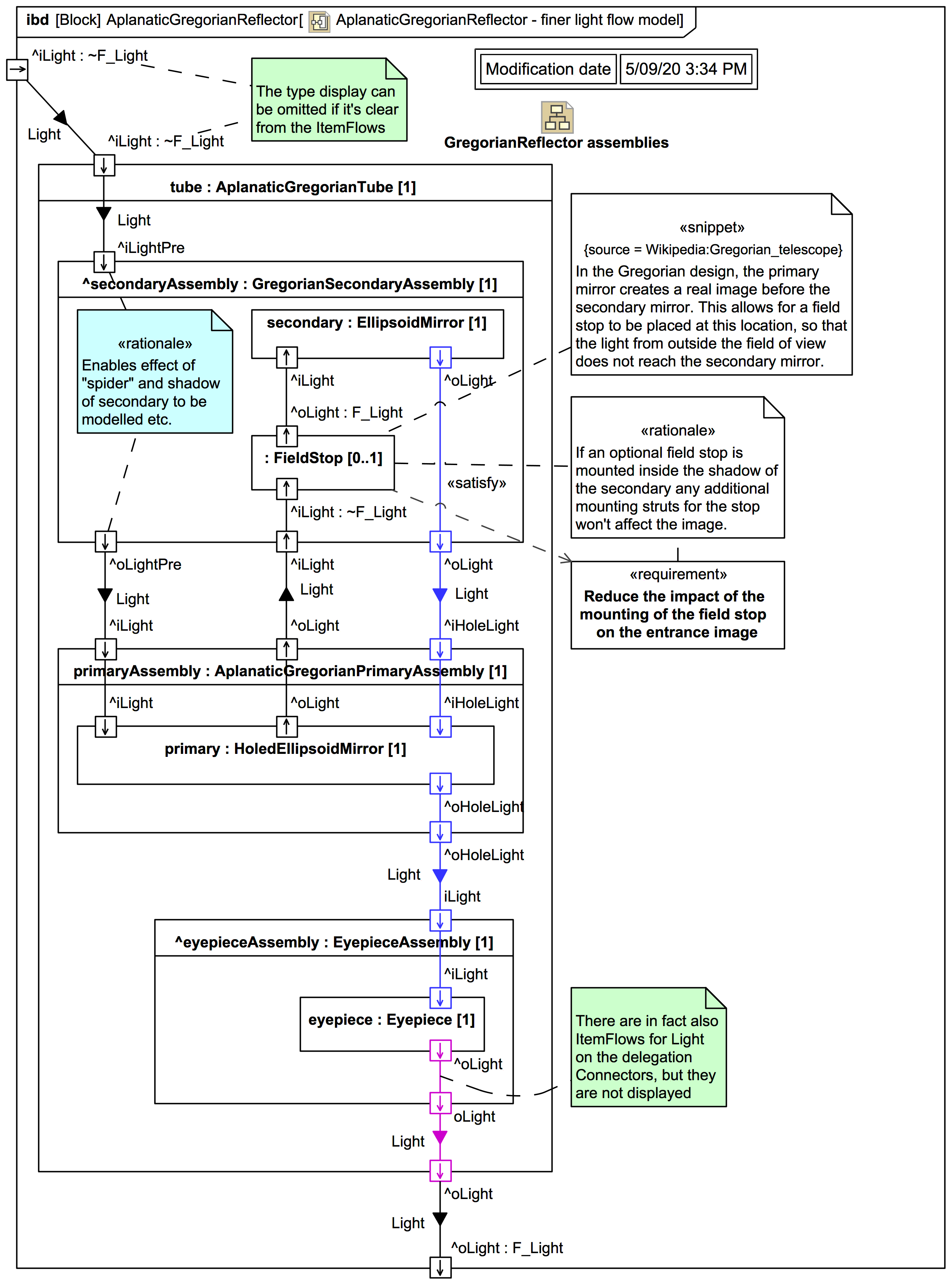
This improves on the previous simple light flow model by including the assemblies. This turns out to be important for more complex telescopes.
Consider, for example, the secondary assembly, recalling it acts as a spatial zone. The light entering the tube in fact passes through the secondary assembly zone (shown here as Ports iLightPre and iLightPre), and if the secondary mirror is mounted with "spiders" they will affect the light and cause diffraction spikes. The secondary mirror itself also causes a shadow, and reduces the total intensity of collected light compared with that entering the tube. The actual effect is not modelled yet, that would require knowledge of a specific secondary mounting system etc. So the light flow model does not (yet) have internal Connectors for that section; the Light just comes in the iLightPre and then re-appears at the iLightPre port.
To perform actual optics calculations requires, of course, additional information about the geometry and the optical elements not yet included in the model.
This strategy shown can be extended beyond physical assemblies. One can introduce spatial zones that "wrap" any physical parts or assemblies. This turns out to be useful when modelling complex telescopes with multi-segment mirror assemblies like the Giant Magellan Telescope.
This finer light flow model also introduces a new :FieldStop[0..1] element:
This choice of associating :FieldStop with the secondary assembly is a place-holder design choice, it is not necessarily how it is implemented on every Gregorian. The idea as shown is to avoid having any additional mounting struts for a stop in the way of the light after it has entered the tube and passed the secondary mirror (in order to «satisfy» a Requirement); the mounting struts for the stop could, for example, be attached to the same spider that holds the secondary mirror. This does not necessarily imply that the field stop is placed before the primary focus or after it (yet); this must however be carefully considered in an image flow model.