
Given that the SysML language is a set of MBSE building blocks, not itself a methodology, there are few modelling areas where there are more modelling options and valid choices with pros and cons than this one. Before examining some popular options in more detail, please note carefully:
Sequence Diagrams for Interactions have proven very popular for communicating with a wide range of stakeholders, even those not fluent in SysML, and they can show timing and related constraints easily. By their nature, they march through a particular scenario in a clear and accessible way, and they appear as the preferred choice for scenario modelling in many older UML-based discussions of UseCase drill-down.
A SysML Activity Diagrams with swimlanes works well with SysML Allocations, but it is not suitable for indicating timings. Webel recommends use of SysML Activity Diagrams with swimlanes in cases where timing is not important.
There are pros and cons, and your best choice depends on the system, your domain, and the stakeholder audience also.
It is often implied or assumed in tutorial slides and videos and other presentations on SysML for MBSE that you somehow must (or should) exclusively choose between using a Sequence Diagram (for an Interaction) or a SysML Activity Diagram, when you can in fact have both; just make one the "primary" and relate it to the other, which you can do with a SysML Refine (or a Trace, but in the Webel recipe Refine is preferred for UseCase drill down). It is, however, true that in SysMLv1 you can then have fiddly coordination issues across them; SysMLv2 has better support for integration of all behavioural aspects across the entire model.
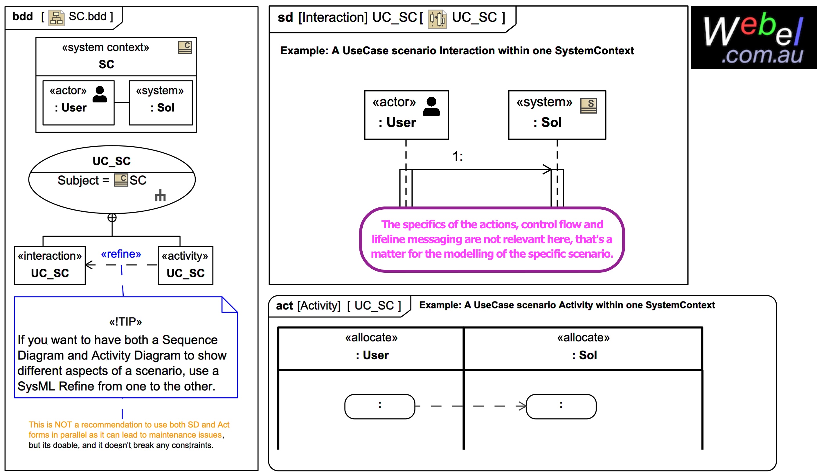
In both the case of using Sequence Diagrams or Activity Diagrams with allocation swimlanes, the following recommendation holds, as described here for a a single block-based «actor» interacting with a system of interest:
- SD: The «actor» is on the 1st (by popular convention left) Lifeline, the System is on the 2nd Lifeline.
- ACT: The «actor» is on the 1st (left) swimlane, the System is on the 2nd swimlane (both either as Classifiers or as usages, depending on your chosen approach).
This is shown for each in the image above of a UseCase UC_SC with a SystemContext SC as 'subject' (being just one popular modelling approach).
(The specifics of the actions, control flow and lifeline messaging are not relevant here, that's a matter for the modelling of the specific scenario).
Webel recommends the use of the usage-based allocation approach over the Classifier-based approach.
MagicDraw/Cameo has nice SysML Activity Diagram support for automatically detecting the part properties of a Block (which happens here to be the 'subject' of a UseCase) and offering them as usages on the allocation swimlanes.
If you are wisely using a block-based custom «actor» (an extension of the non-normative External is recommend by Webel), and if you have a particular SystemContext as the 'subject' of your UseCase, you'll have something like :User and :System as SysML part properties of that particular SystemContext block, which is the MagicGrid approach: